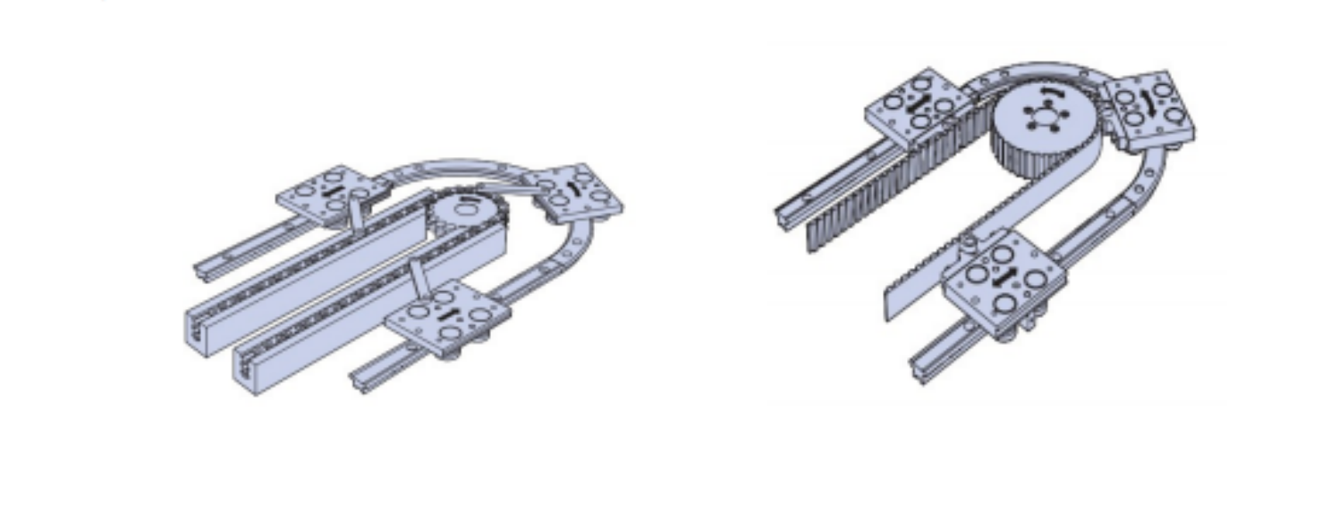
Die Installationsmethode ist flexibler. Der zahnradgetriebene Schlitten bewegt sich bogenförmig auf der Bogenführungsschiene.
YOSO-Rundführungsschienenserie
Die Bogenlinearführung verfügt über lineare Führungsschienen vom Rollentyp und lineare Führungsschienen vom Kugeltyp. Kann eine Präzisionsringführungsschiene bilden. In Verbindung mit dem Antriebssystem kann es eine Präzisionsringmontagelinie, eine Ringproduktionslinie oder eine Ringmontagelinie und andere Zykluslinien bilden. Diese Art von Führungszirkulationsleitung, kompaktere Struktur, höhere Positionierungsgenauigkeit, mehr Konfigurationsmöglichkeiten; In vielerlei Hinsicht übertrifft es herkömmliche Lieferlinien.
In modernen Produktionsfabriken, die ständig nach Möglichkeiten suchen, die Produktionskosten zu senken, besteht eine Automatisierungsrichtung darin, jede Station so nah wie möglich beieinander anzuordnen, den Werkstückabstand zwischen den Stationen zu verringern und den Platzbedarf zu minimieren. Um dies zu erreichen, müssen Sie Wenn das Werkstück eine Ringbewegung ausführen muss, müssen Sie eine Ringlinie verwenden. Es gibt zwei Arten von Ringdrähten: herkömmliche Drähte ohne Führung und Präzisionsdrähte, die wie folgt beschrieben werden:
Traditioneller Gürteltyp
Die Bandförderlinie ist eine relativ einfache Struktur, ein breites Förderband um zwei Rollen, die durch einen bestimmten Abstand voneinander getrennt sind. Die Rollendrehung, die Bewegung des Förderbands und der Antrieb des Werkstücks auf dem Band bewegen sich. Rollenförderstrecke und Bandförderstrecke, das Prinzip ist ähnlich, nur dass das Band durch eine Reihe dicht angeordneter Trommeln ersetzt wird.
Ohne Führungsbahn ist das Werkstück auf dem Riemen oder der Rolle befestigt, nicht starr, wird durch die Reibungskraft der Schwerkraft erzeugt und kann die Bewegung des Werkstücks nach links und rechts, nach vorne, hinten und nach oben nicht gut einschränken. Um ein Herausfallen des Werkstücks zu verhindern, ist es notwendig, auf beiden Seiten des Bandes oder der Trommel ein Prallblech anzubringen. Da das Werkstück nicht am Band oder an der Rolle befestigt ist, vibriert das Werkstück häufig; Wenn die Form des Werkstücks komplexer ist, verklebt es oft mit den Teilen der Förderstrecke. Durch die durch die Schwerkraft erzeugte Reibung zur Fixierung des Werkstücks auf der Förderstrecke kann keine gute Positionierungsgenauigkeit gewährleistet werden, mehr nicht Stellen Sie die Förderstrecke senkrecht auf. Das Feste
Das Werkstück ist nicht starr, was die Bewegungsgeschwindigkeit der Förderstrecke begrenzt.
Das Werkstück ist auf dem Schlittensitz fixiert, der Schlittensitz rollt über die Rolle auf der Führungsschiene, die Führungsschiene schränkt die Freiheit des Schlittensitzes sehr stark ein, nur eine Bewegungsfreiheitsrichtung. Daher erfüllen Ringleitungen vom Führungsbahntyp mit höherer Geschwindigkeit und höherer Positionierungsgenauigkeit die Anforderungen der Präzisionsautomatisierung.
Zusammenfassend lässt sich sagen, dass, wenn Sie auf kleinem Raum arbeiten müssen, um eine präzise Automatisierung zu erreichen: Werkstücke sich schnell zwischen den Stationen bewegen; Nach dem Stoppen der Bewegung weist das Werkstück eine gute Positionsgenauigkeit auf; Nach dem Stoppen der Bewegung kann zur Bearbeitung oder Montage zusätzliche Kraft auf das Werkstück ausgeübt werden; Dann können Sie eine präzise Ringführung als Grundlage für die Gestaltung Ihrer Ringleitung wählen.
Es gibt zwei Hauptwellen, um ringförmige Führungsschienen für ringförmige Leitungen zu verwenden: Landebahnform und Quadrat:
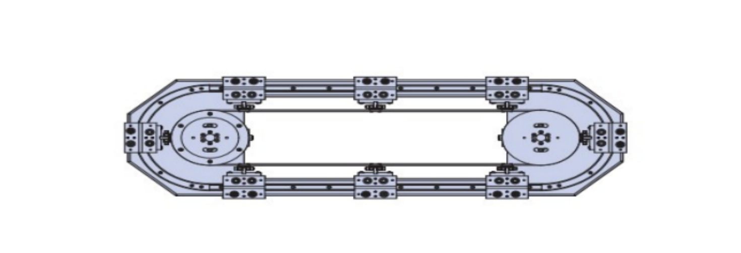
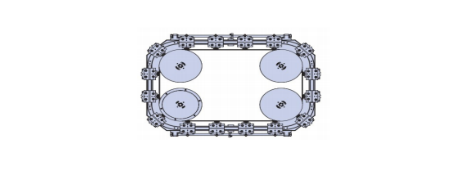
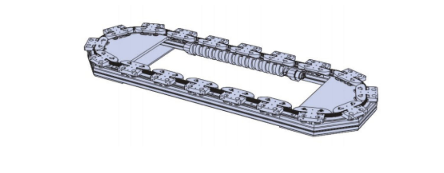
Die bogenförmige Linearführung wird in Verbindung mit dem Antriebssystem zu einer ringförmigen Montagelinie. Derzeit gibt es drei Hauptantriebsmodi: Kettentyp, Synchronriementyp und Mannschaftstyp:
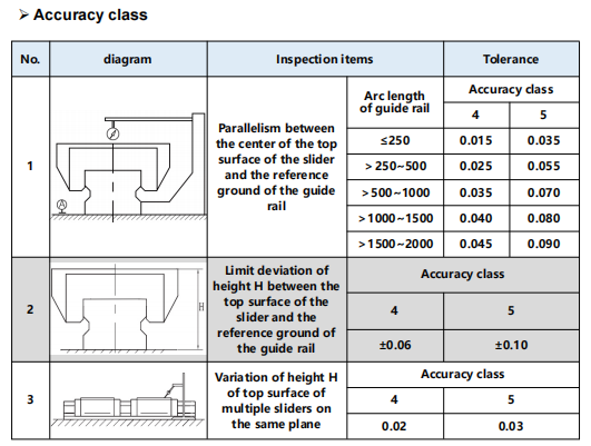
| Modell | Führungsschienengröße | Slider-Größe | Größe des Ölbechers | ||||||||||
| H | B1 | B2 | B3 | K | L1 | L2 | L3 | M | Ф | L4 | G | N | |
| YCR16/168AA(AB) | 24 | 47 | 4.5 | 38 | 19.4 | 58 | 40.5 | 30 | MS | 4.5 | 7 | M4 | 4 |
| YCR16/228AA(AB) | 24 | 47 | 4.5 | 38 | 19.4 | 58 | 40.5 | 30 | MS | 4.5 | 7 | M4 | 4 |
| YCR16/300AA(AB) | 24 | 47 | 4.5 | 38 | 19.4 | 58 | 40.5 | 30 | MS | 4.5 | 7 | M4 | 4 |
| YCR16/390AA(AB) | 24 | 47 | 4.5 | 38 | 19.4 | 58 | 40.5 | 30 | MS | 4.5 | 7 | M4 | 4 |
| YCR25/230AA(AB) | 36 | 70 | 6.5 | 57 | 28.8 | 79.5 | 59 | 45 | M8 | 7 | 11 | M6 | 6 |
| YCR25/400AA(AB) | 36 | 70 | 6.5 | 57 | 28.8 | 79.5 | 59 | 45 | MB | 7 | 11 | M6 | 6 |
| YCR25/500AA(AB) | 36 | 70 | 6.5 | 57 | 28.8 | 79.5 | 59 | 45 | M8 | 7 | 11 | M6 | 6 |
| YCR25/750AA(AB) | 36 | 70 | 6.5 | 57 | 28.8 | 79.5 | 59 | 45 | M8 | 7 | 11 | M6 | 6 |
| YCR25/1000AA(AB) | 36 | 70 | 6.5 | 57 | 28.8 | 79.5 | 59 | 45 | M8 | 7 | 11 | M6 | 6 |
| YCR35/600AA(AB) | 48 | 100 | 9 | 82 | 38 | 111 | 81 | 58 | M10 | 11 | 11 | M6 | 8 |
| YCR35/800AA(AB) | 48 | 100 | 9 | 82 | 38 | 111 | 81 | 58 | M10 | 11 | 11 | M6 | 8 |
| YCR35/1000AA(AB) | 48 | 100 | 9 | 82 | 38 | 111 | 81 | 58 | M10 | 11 | 11 | M6 | 8 |
| YCR35/1300AA(AB) | 48 | 100 | 9 | 82 | 38 | 111 | 81 | 58 | M10 | 11 | 11 | M6 | 8 |
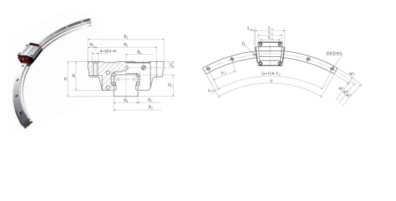
| Guide-Rall-Vererber | Minimaler Endwinkel | Bewertete dynamische Belastung | Statische Nennlast | Bewertetes statisches Moment | Slide wright kg | Rollengewicht kg/m | Modell | |||||||||
| B4 | H1 | daDuh | Θ | RΘ | R1 | R2 | Ich bin | Θ1 | C (MN) | (KN) | MA (Nm) | Mb (N·m) | Mc (Nm) | |||
| 16 | 15 | 4.5 x 7.5 x 5.3 | 15° | 168 | 160 | 176 | 160° | 3° | 5.67 | 6.35 | 51.8 | 51.8 | 829 | 0.2 | 1.5 | YCR16/16BAA(AB) |
| 16 | 15 | 45 x 7.5 x 5.3 | 15° | 228 | 220 | 236 | 160° | 3° | 5.67 | 6.35 | 51.8 | 51.8 | 829 | 0.2 | 15 | YCR:16/228AA(AB) |
| 16 | 15 | 45 x 7.5 x 5.3 | 15° | 300 | 292 | 30 g | 75° | 2° | 5.67 | 6.35 | 51.8 | 51.8 | 829 | 0.2 | 1.5 | VCR16/30GAA(AB) |
| 16 | 15 | 4.5 x 7.5 x 5.3 | 15 | 390 | 382 | 398 | 65° | 2° | 5.67 | 6.35 | 51.8 | 51.8 | 829 | 0.2 | 1.5 | YCR 16/39GAA(AB) |
| 23 | 22 | 7 x 11 x 9 | 15° | 230 | 218.5 | 241.5 | 160° | 3° | 16.8 | 21.5 | 142.2 | 142.2 | 233.5 | 0.59 | 3.3 | YCR25/23GAA(AB) |
| 23 | 22 | 7 x 11 x 9 | 10° | 400 | 388.5 | 411.5 | 60° | 2° | 16.8 | 21.5 | 142.2 | 1422 | 233.5 | 0.99 | 3.3 | YCR25/40GAA(AB) |
| 23 | 22 | 7x11x | 7° | 500 | 488.5 | 511.5 | 60° | 2° | 168 | 21.5 | 142.2 | 1422 | 233.5 | 0.99 | 3.3 | YCR25/SOGAA(AB) |
| 23 | 22 | 7 x 11 x 9 | 5* | 750 | 738.5 | 751.5 | 35° | 2° | 16.8 | 21.5 | 142.2 | 142.2 | 233.5 | 0.99 | 3.3 | YCR25/75GAA(AB) |
| 23 | 22 | 7x11x | 4° | 10:00 | 988.5 | 1011.5 | 28° | 2° | 16.8 | 21.5 | 142.2 | 1422 | 233.5 | 0.99 | 33 | YCR25/1000A.A(AB) |
| 34 | 29 | 9 x 14 x 12 | 9" | 600 | 583 | 617 | 60° | 2° | 3497 | 58.53 | 610 | 610 | 1030 | 1.4 | 6.5 | YCR 3S/SOGAA(AB) |
| 34 | 29 | 9 x 14 x 12 | 5.5 | 800 | 783 | 817 | 35° | 2* | 34.97 | 58.53 | 610 | 610 | 1030 | 1.4 | 6.5 | VCR 35/BOGAA(AB) |
| 34 | 29 | 9 x 14 x 12 | 5° | 1000 | 983 | 1017 | 28 * | 2* | 34.97 | 58.53 | 610 | 610 | 1030 | 1.4 | 65 | YCR3S/1000AA(AB) |
| 34 | 29 | 9 x 14 x 12 | 3.5 | 1300 | 1283 | 1317 | 22° | 2* | 34.97 | 58.53 | 610 | 610 | 1030 | 1.4 | 6.5 | YCR35/1300AA(AB) |
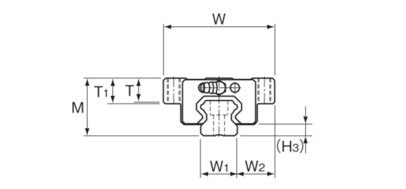
| Modell Nr. | Außenmaße | Abmessungen des Führungswagens | H3 | ||||||||||
| Höhe M | Breite W | Länge L | B | C | S | L1 | T | T1 | N | E | Schmiernippel | ||
| YCR15A+60/150R | 24 | 47 | 54.5 | 38 | 24 | M5 | 38.8 | 10.3 | 11 | 45 | 5.5 | PB1021B | 4.8 |
| YCR15A+60/300R | 55.5 | 28 | |||||||||||
| YCR15A+60/400R | 55.8 | 28 | |||||||||||
| YCR25A+60/500R | 36 | 70 | 81.6 | 57 | 45 | MB | 59.5 | 149 | 16 | 6 | 12 | B-M6F | 7 |
| YCR25A+60/750R | 82.3 | ||||||||||||
| YCR25A+60/1000R | 82.5 | ||||||||||||
| YCR35A+60/600R | 48 | 100 | 107.2 | 82 | 58 | M10 | 80.4 | 19.9 | 21 | 8 | 12 | B-M6F | 8.5 |
| YCR35A+60/800R | 107.5 | ||||||||||||
| YCR35A+60/1000R | 108.2 | ||||||||||||
| YCR35A+60/1300R | 108.5 | ||||||||||||
| YCR45A+60/800R | 60 | 120 | 136.7 | 100 | 70 | M12 | 98 | 239 | 25 | 10 | 16 | B-PT1/8 | 11.5 |
| YCR45A+60/1000R | 137.3 | ||||||||||||
| YCR45A+60/1200R | 137.3 | ||||||||||||
| YCR45A+60/1600R | 138 | ||||||||||||
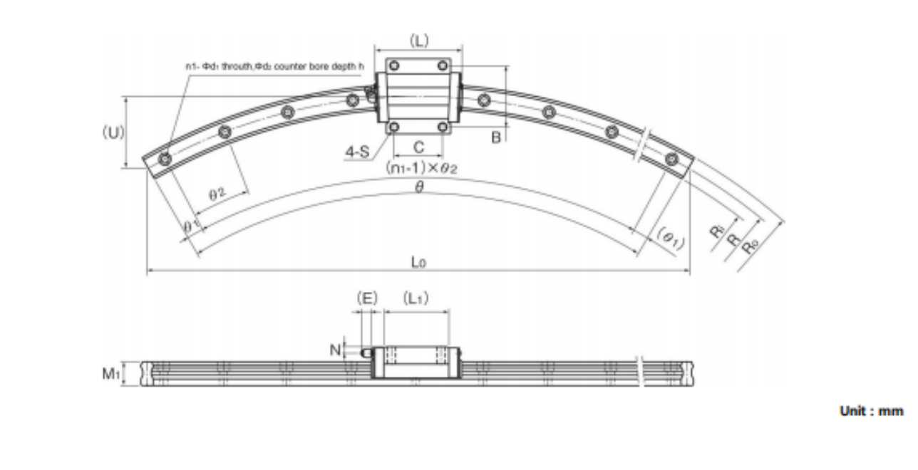
| Abmessungen der LM-Schiene | Grundtragfähigkeit | Statisch zulässiges Moment kN·m | Masse | ||||||||||||||||||
| R | RO | Ri | LO | U | Breite W1 | W2 | Höhe M1 | d1xd2xh | m1 | Θ° | Θ° | Θ2 | kN | CO kN | MA | MB 0 | MC 6 | Führungswagen kg | LM Ral kg/m | ||
| 1 Block | Doppelblöcke | 1 Block | Doppelblöcke | 1 Block | |||||||||||||||||
| 150 | 157.5 | 142.5 | 150 | 20.1 | 15 | 16 | 15 | 4.5 x 7.5 x 5.3 | 3 | 7 | 23 | 6.66 | 10.8 | 0.0805 | 0.457 | 0.080 5 | 0.457 | 0.084 4 | 0.2 | 1.5 | |
| 300 | 307.5 | 2925 | 300 | 40 | 5 | 6 | 12 | 8.33 | 13.5 | ||||||||||||
| 400 | 407.5 | 392.5 | 400 | 54 | 7 | 3 | 9 | 8.33 | 13.5 | ||||||||||||
| 500 | 511.5 | 488.5 | 500 | 67 | 23 | 23.5 | 22 | 7 x 11 x 9 | 9 | 2 | 7 | 19.9 | 344 | 0.307 | 1.71 0 | .307 | 1.71 | 0.344 | 0.59 | 3.3 | |
| 750 | 761.5 | 738.5 | 750 | 100 | 12 | 2.5 | 5 | ||||||||||||||
| 1000 | 1011.5 | 988.5 | 1000 | 134 | 15 | 2 | 4 | ||||||||||||||
| 600 | 617 | 583 | 600 | 80 | 34 | 33 | 29 | 9 x 14 x 12 | 7 | 3 | 9 | 37.3 | 61.1 | 0.782 | 3.93 0 | .782 | 3.93 | 0.905 | 1.6 | 6.6 | |
| 800 | 817 | 793 | 800 | 107 | 11 | 2.5 | 5.5 | ||||||||||||||
| 1000 | 1017 | 983 | 1000 | 134 | 12 | 2.5 | 5 | ||||||||||||||
| 1300 | 1317 | 1283 | 1300 | 174 | 17 | 2 | 3.5 | ||||||||||||||
| 800 | 822.5 | 777.5 | 800 | 107 | 45 | 37.5 | 38 | 14 x 20 x 17 | 8 | 60 | 2 | 8 | 60 | 95.6 | 1.42 | 7.92 | 1.42 | 7.92 | 1.83 | 2.8 | 11.0 |
| 1000 | 1022.5 | 977.5 | 1000 | 134 | 10 | 3 | 6 | ||||||||||||||
| 12.00 | 1222.5 | 1177.5 | 1200 | 161 | 12 | 2.5 | 5 | ||||||||||||||
| 1600 | 1622.5 | 1577.5 | 1600 | 214 | 15 | 2 | 4 | ||||||||||||||
Copyright © Jingpeng Machinery&Equipment(Shanghai) Co.,Ltd. Alle Rechte vorbehalten