| Product Name: | Modulus: | Screw shaft outer diameter: |
| External circulation large load screw | FDW | 25-100 |
| Overall length: | Outer diameter: | Accuracy level: |
| 40-251 | 50-170 | C5 |
External circulation large load screw High precision intubation screw The cannula screw is a linear transmission element widely used in precision machinery, automation equipment and industrial control systems. With its high precision, high load-bearing capacity and stability, the cannula screw can provide smooth and reliable motion control in harsh industrial environments. It adopts a unique structural design, which effectively reduces the transmission error and provides a smoother running trajectory.
The cannula screws we provide have a variety of specifications and models, which can be customized according to customer needs. They are widely used in CNC machine tools, robot systems, automated production lines and other fields to meet the requirements of various equipment for precision transmission and high load support.
External circulation large load screw High precision intubation screw
1.Structure and specialties
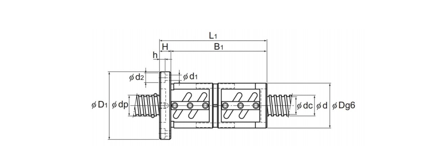
Unprocessed products at the end of the shaft are produced by standardizing the screw shaft of precision ball screws and process.ing it into a series of mass-produced products of specified length. The screw shaft end is easy to be machined.In addition, there are single nut FDW type and double nut FDDw type nut models. Please choose the appropriate type accordingto the purpose of use.
2.dustproof
When dirt or other foreign obiects may enter the ball screw, a dust-proof device (such as a telescopic cover, etc, must be used to completely cover the screw shaft.
3.lubrication
For nuts, lithium soap based lubricating oil has been sealed at the time of delivery.
4.Additional processing of the screw shaft end
Due to the fact that only the efective threaded portion of the screw shaft is surface hardened through induction hardening or carburizing treatment,it is very easy to perform additional machining on the shaft end through a grinder or milling machine.In addition, as both ends of the screw shaft have central holes, they can accept external cylindrical grinding processing.
Surface hardness of effective threads:58 to 64HRC
Surface hardness of the end of the screw shaft
FDW.FDDWmodel:22 t0 27HRC
| ModelNo | Screw shaftouter diameter |
Lead | Ball center- to-center diameter |
Thread minor diameter |
No.of loaded circuits |
Basic load rating | Rigidity k N/μm |
|
Ca kN |
Coa kN |
|||||||
| d | ph | dp | dc | RowS x turns | ||||
| FDW2505V-2.5 | 25 | 5 | 25.75 | 22.2 | 1×2.5 | 9.2 | 21.9 | 240 |
| FDW2505V-5 | 25 | 5 | 25.75 | 22.2 | 2×2.5 | 16.7 | 43.9 | 460 |
| FDW2506V-2.5 | 25 | 6 | 26 | 21.4 | 1×2.5 | 12.4 | 27.4 | 250 |
| FDW2506V-5 | 25 | 6 | 26 | 21.4 | 2×2.5 | 22.6 | 54.8 | 470 |
| FDW2805V-2.5 | 28 | 5 | 28.75 | 25.2 | 1×2.5 | 9.7 | 24.6 | 250 |
| FDW2805V-5 | 28 | 5 | 28.75 | 25.2 | 2×2.5 | 17.5 | 49.2 | 500 |
| FDW2805V-7.5 | 28 | 5 | 28.75 | 25.2 | 3×2.5 | 24.8 | 73.8 | 740 |
| FDW2806V-2.5 | 28 | 6 | 28.75 | 25.2 | 1×2.5 | 9.6 | 24.6 | 250 |
| FDW2806V-5 | 28 | 6 | 28.75 | 25.2 | 2×2.5 | 17.5 | 49.2 | 500 |
| FDW2806V-7.5 | 28 | 6 | 28.75 | 25.2 | 3×2.5 | 24.8 | 73.8 | 740 |
| FDW3205V-2.5 | 32 | 5 | 32.75 | 29.2 | 1×2.5 | 10.2 | 28.1 | 280 |
| FDW3205V-5 | 32 | 5 | 32.75 | 29.2 | 2×2.5 | 18.5 | 56.3 | 560 |
| FDW3205V-7.5 | 32 | 5 | 32.75 | 29.2 | 3×2.5 | 26.2 | 84.4 | 810 |
| FDW3206V-2.5 | 32 | 6 | 33 | 28.4 | 1×2.5 | 13.9 | 35.2 | 290 |
| FDW3206V-5 | 32 | 6 | 33 | 28.4 | 2×2.5 | 25.2 | 70.3 | 580 |
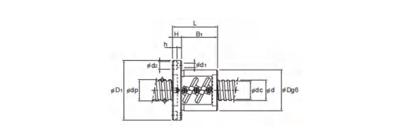
| Nut dimensions | Screw shaft inertial moment/mm |
Nut mass |
Shaft mass |
|||||||
Outer diameter |
Flange diameter |
Overall length |
Lubrication hole |
|||||||
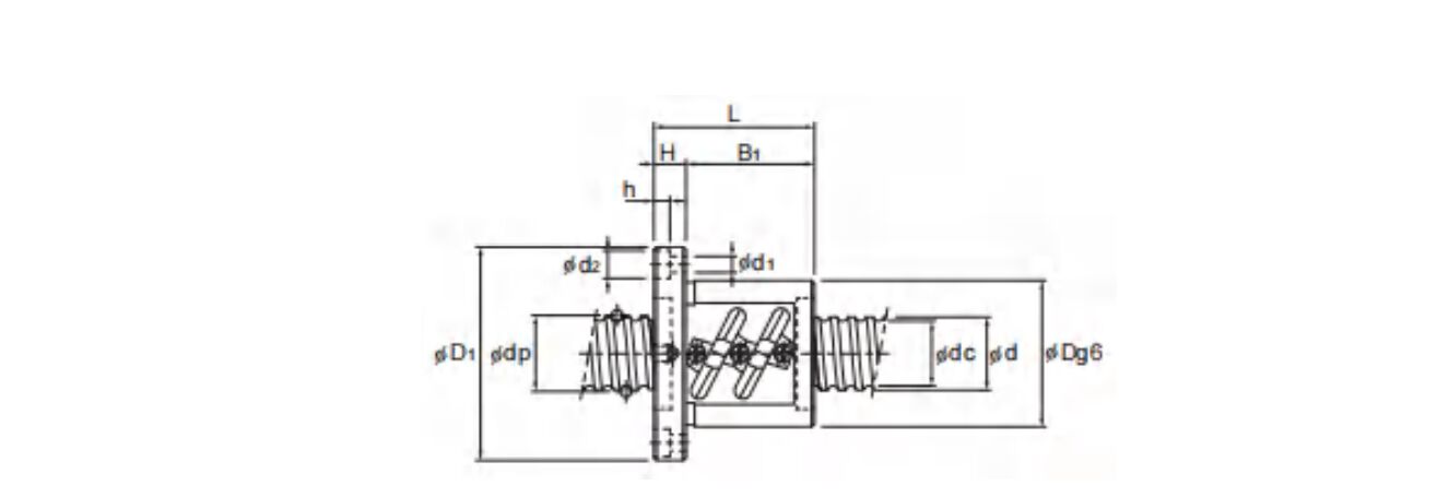
| D | D₁ | L₁ | H | B₁ | PCD | d₁ ×d₂xh | A | kg m²/mm | kg | kg/m |
| 50 | 73 | 40 | 11 | 29 | 61 | 5.5×9.5×5.5 | M6 | 3.01×10⁻³ | 0.52 | 3.52 |
| 50 | 73 | 5 . |
11 | 44 | 61 | 5.5×9.5×5.5 | M6 | 3.01×10- | 0.68 | 3.52 |
| 53 | 76 | 44 | 11 | 33 | 64 | 5.5×9.5×5.5 | M6 | 3.01×10⁻³ | 0.61 | 3.43 |
| 53 | 76 | 62 | 11 | 51 | 64 | 5.5×9.5×5.5 | M6 | 3.01×10⁻³ | 0.91 | 3.43 |
| 55 | 85 | 44 | 12 | 32 | 69 | 6.6×11×6.5 | M6 | 4.74×10⁻³ | 1.02 | 4.45 |
| 55 | 85 | 59 | 12 | 47 | 69 | 6.6×11×6.5 | M6 | 4.74×10⁻³ | 1.06 | 4.45 |
| 55 | 85 | 74 | 12 | 62 | 69 | 6.6×11X6.5 | M6 | 4.74×10⁻³ | 1.16 | 4.45 |
| 55 | 85 | 50 | 12 | 38 | 69 | 6.6×11×6.5 | M6 | 4.74×10⁻³ | 0.87 | 4.52 |
| 5 | 85 | 68 | 12 | 56 | 69 | 6.6×11X6.5 | M6 | 4.74×10⁻³ | 1.09 | 4.52 |
| 55 | 85 | 86 | 12 | 74 | 69 | 6.6×11×6.5 | M6 | 4.74×10⁻³ | 1.3 | 4.52 |
| 58 | 85 | 41 | 12 | 29 | 71 | 6.6×11×6.5 | M6 | 8.08×10⁻³ | 0.76 | 5.89 |
| 58 | 85 | 56 | 12 | 44 | 71 | 6.6×11×6.5 | M6 | 8.08×10⁻³ | 0.94 | 5.89 |
| 58 | 85 | 71 | 12 | 59 | 71 | 6.6×11X6.5 | M6 | 8.08×10-³ | 1.13 | 5.89 |
| 62 | 89 | 45 | 12 | 33 | 75 | 6.6×11×6.5 | M6 | 8.08×10⁻³ | 0.94 | 5.88 |
| 62 | 89 | 63 | 12 | 51 | 75 | 6.6×11X6.5 | M6 | 8.08×10⁻³ | 1.21 | 5.88 |

| ModelNo. | SereW shaftouter diameter |
Lead | Ball center- to-center diameter |
Thread minor diameter |
No.of loaded circuits |
Basic load rating | Rigidity k N/μm |
|
Ca kN |
Coa kN |
|||||||
| d | ph | dp | dc | Rowsxturns | ||||
| FDW2508V-2.5 FDW2508V-3.5 |
25 | 8 | 26.25 | 20.5 | 1×2.5 | 15.8 | 32.9 | 250 |
| 25 | 8 | 26.25 | 20.5 | 1×3.5 | 21.1 | 46 | 340 | |
| FDW2508V-5 | 25 | 8 | 26.25 | 20.5 | 2×2.5 | 28.7 | 65.7 | 480 |
| FDW2510V-2.5 | 25 | 10 | 26.25 | 21.5 | 1×2.5 | 15.8 | 32.9 | 250 |
| FDW2810V-2.5 | 28 | 10 | 29.75 | 22.4 | 1×2.5 | 24.3 | 49 | 280 |
| FDW3210V-2.5 | 32 | 10 | 33.75 | 26.4 | 1×2.5 | 26 | 56.2 | 310 |
| FDW3210V-3.5 | 32 | 10 | 33.75 | 26.4 | 1X3.5 | 34.8 | 78.6 | 440 |
| FDW3210V-5 | 32 | 10 | 33.75 | 26.4 | 2×2.5 | 47.3 | 112.3 | 620 |
| FDW3212V-3.5 | 32 | 12 | 34 | 26.1 | 1X3.5 | 40.4 | 88.5 | 440 |
| FDW3216V-5 | 32 | 16 | 33.75 | 26.4 | 2×2.5 | 47.1 | 113.1 | 616 |
| FDW3610V-2.5 | 36 | 10 | 37.75 | 30.5 | 1X2.5 | 27.6 | 63.3 | 350 |
| FDW3610V-5 | 36 | 10 | 37.75 | 30.5 | 2×2.5 | 50.1 | 126.5 | 680 |
| FDW3610V-7.5 | 36 | 10 | 37.75 | 30.5 | 3×2.5 | 71 | 189.8 | 990 |
| FDW3612V-2.5 | 36 | 12 | 38 | 30.1 | 1×2.5 | 32.2 | 71.2 | 350 |
| FDW3612V-5 | 36 | 12 | 38 | 30.1 | 2×2.5 | 58.4 | 142.3 | 690 |
| FDW3616V-2.5 | 36 | 16 | 38 | 30.1 | 1×2.5 | 32.1 | 71.5 | 350 |
| FDW3620V-1.5 | 36 | 20 | 37.75 | 30.5 | 1×1.5 | 17.7 | 38.4 | 215 |
| FDW4010V-2.5 | 40 | 10 | 41.75 | 34.4 | 1×2.5 | 29 | 70.4 | 380 |
| FDW4010V-3.5 | 40 | 10 | 41.75 | 34.4 | 1×3.5 | 38.8 | 98.5 | 520 |
| FDW4010V-5 | 40 | 10 | 41.75 | 34.4 | 2X2.5 | 52.7 | 140.7 | 740 |
| FDW4012V-2.5 | 40 | 12 | 42 | 34.1 | 1X2.5 | 33.9 | 79.2 | 390 |
| FDW4012V-3.5 | 40 | 12 | 42 | 34.1 | 1×3.5 | 45.3 | 110.8 | 530 |
| FDW4012V-5 | 40 | 12 | 42 | 34.1 | 2×2.5 | 61.6 | 158.3 | 750 |
| FDW4016V-5 | 40 | 16 | 42 | 34.1 | 2×2.5 | 61.5 | 158.8 | 740 |
| FDW4020V-5 | 40 | 20 | 41.75 | 34.4 | 2×2.5 | 52.4 | 142 | 736 |
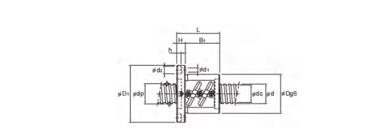
| Nut dimensions | Screw shaft inertial moment/mm |
Nut mass |
Shaft ma55 |
|||||||
| Outer diameter |
Flange diameten |
Overall length |
Lubriation hole |
|||||||
| D | D₁ | L | H | B₁ | PCD | dix d xh | A | kg m²/mm | kg | kg/m |
| 58 | 85 | 58 | 15 | 43 | 71 | 6.6×11×6.5 | M6 | 3.10×10⁻³ | 1.07 | 3.51 |
| 58 | 85 | 66 | 15 | 51 | 71 | 6.6×11×6.5 | M6 | 3.10X10- | 1.29 | 3.51 |
| 58 | 85 | 82 | 15 | 67 | 71 | 6.6×11×6.5 | M6 | 3.10×10⁻³ | 1.44 | 3.51 |
| 58 | 85 | 70 | 18 | 52 | 71 | 6.6×11×6.5 | M6 | 3.10X10⁻³ | 1.43 | 3.5 |
| 65 | 106 | 86 | 18 | 68 | 85 | 11×17.5×11 | M6 | 4.74×10⁻³ | 2.3 | 4.15 |
| 74 | 108 | 70 | 15 | 55 | 90 | 9×14X8.5 | M6 | 8.08×10⁻³ | 2.2 | 5.53 |
| 74 | 108 | 80 | 15 | 65 | 90 | 9X14X8.5 | M6 | 8.08X10⁻³ | 2.44 | 5.53 |
| 74 | 108 | 100 | 15 | 85 | 90 | 9×14X8.5 | M6 | 8.08×10⁻³ | 2.92 | 5.53 |
| 76 | 121 | 98 | 18 | 80 | 98 | 11X17.5X11 | M6 | 8.08×10⁻³ | 3.4 | 5.7 |
| 74 | 108 | 139 | 18 | 121 | 90 | 9×14X8.5 | M6 | 8.08×10⁻³ | 3.81 | 5.82 |
| 75 | 120 | 81 | 18 | 63 | 98 | 11X17.5X11 | M6 | 1.29×10⁻² | 2.75 | 7.1 |
| 75 | 120 | 111 | 18 | 93 | 98 | 11X17.5X11 | M6 | 1.29×10⁻² | 3.45 | 7.1 |
| 75 | 120 | 141 | 18 | 123 | 98 | 11X17.5×11 | M6 | 1.29X10⁻² | 4.15 | 7.1 |
| 78 | 123 | 87 | 18 | 69 | 100 | 11×17.5×11 | M6 | 1.29X10⁻² | 3.14 | 7.99 |
| 78 | 123 | 123 | 18 | 105 | 100 | 11X17.5X11 | M6 | 1.29×10⁻² | 4.07 | 7.99 |
| 78 | 123 | 92 | 18 | 74 | 100 | 11×17.5×11 | M6 | 1.29X10⁻² | 3.27 | 7.99 |
| 75 | 114 | 82 | 18 | 64 | 93 | 11X17.5X11 | M6 | 1.29×10⁻² | 2.38 | 7.54 |
| 82 | 124 | 73 | 18 | 55 | 102 | 11×17.5×11 | M6 | 1.97×10⁻² | 2.86 | 8.87 |
| 82 | 124 | 83 | 18 | 65 | 102 | 11X17.5×11 | M6 | 1.97×10- | 3.14 | 8.87 |
| 82 | 124 | 103 | 18 | 85 | 102 | 11×17.5×11 | M6 | 1.97×10⁻² | 3.69 | 8.87 |
| 84 | 126 | 83 | 18 | 65 | 104 | 11X17.5×11 | M6 | 1.97×10⁻² | 3.31 | 8.83 |
| 84 | 126 | 95 | 18 | 77 | 104 | 11×17.5×11 | M6 | 1.97X10- | 3.66 | 8.83 |
| 84 | 126 | 119 | 18 | 101 | 104 | 11×17.5×11 | M6 | 1.97X10⁻² | 4.36 | 8.83 |
| 84 | 126 | 144 | 18 | 126 | 104 | 11×17.5×11 | M6 | 1.97X10⁻² | 5.52 | 9.09 |
| 82 | 126 | 162 | 18 | 144 | 104 | 11X17.5×11 | M6 | 1.97×10⁻² | 5.17 | 9.37 |

| Model No. | Screw shaft outer diameter |
Lead | Ball center- to-center diameter |
Thread minor diameter |
No.of loaded circuits |
Basic load rating | Rigidity k N/μm |
|
Ca kN |
Coa kN |
|||||||
| d | ph | dp | dc | Rows xturns | ||||
| FDW4510V-2.5 | 45 | 10 | 46.75 | 39.5 | 1×2.5 | 30.6 | 79.3 | 420 |
| FDW4510V-3 | 45 | 10 | 46.75 | 39.5 | 2×1.5 | 35.8 | 95.1 | 500 |
| FDW4510V-5 | 45 | 10 | 46.75 | 39.5 | 2×2.5 | 55.6 | 158.5 | 800 |
| FDW4510V-7.5 | 45 | 10 | 46.75 | 39.5 | 3×2.5 | 78.8 | 237.8 | 1190 |
| FDW4512V-5 | 45 | 12 | 47 | 39.2 | 2×2.5 | 65.2 | 178.3 | 820 |
| FDW4520V-2.5 | 45 | 20 | 47 | 39.2 | 1×2.5 | 35.8 | 89.7 | 424 |
| FDW5010V-2.5 | 50 | 10 | 51.75 | 44.4 | 1×2.5 | 32.1 | 88.1 | 450 |
| FDW5010V-3.5 | 50 | 10 | 51.75 | 44.4 | 1×3.5 | 42.9 | 123.4 | 620 |
| FDW5010V-5 | 6 | 10 | 51.75 | 44.4 | 2×2.5 | 58.2 | 176.3 | 880 |
| FDW5010V-7.5 | 50 | 10 | 51.75 | 44.4 | 3×2.5 | 82.5 | 264.4 | 1290 |
| FDW5012V-2.5 | 50 | 12 | 52.25 | 43.3 | 1×2.5 | 43.4 | 110.1 | 470 |
| FDW5012V-3.5 | 50 | 12 | 52.25 | 43.3 | 1×3.5 | 58 | 154.1 | 640 |
| FDW5012V-5 | 50 | 12 | 52.25 | 43.3 | 2×2.5 | 78.8 | 220.2 | 910 |
| FDW5016V-2.5 | 50 | 16 | 52.7 | 42.9 | 1×2.5 | 72.6 | 183.1 | 620 |
| FDW5016V-5 | 50 | 16 | 52.7 | 42.9 | 2×2.5 | 131.8 | 366.2 | 1180 |
| FDW5020V-2.5 | 50 | 20 | 52.7 | 42.9 | 1×2.5 | 72.5 | 183.6 | 620 |
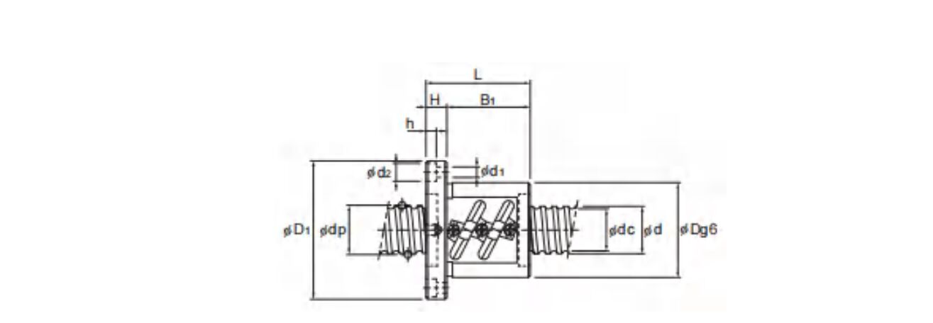
| Nut dimensions | Screw shaft inertial moment/mm |
Nut masS |
Shaft mass |
|||||||
| Outer diameter |
Flange diameter |
Overall length |
Lubrication hole |
|||||||
| D | D₁ | Li | H | B₁ | PCD | d₁xd₂xh | A | kg m²/mm | kg | kg/m |
| 88 | 132 | 81 | 18 | 63 | 110 | 11×17.5×11 | 3.16×10⁻² | 3.43 | 11.36 | |
| 88 | 132 | 94 | 18 | 76 | 110 | 11×17.5×11 | 3.16×10⁻² | 3.83 | 11.36 | |
| 88 | 132 | 111 | 18 | 93 | 110 | 11×17.5×11 | 3.16×10⁻² | 4.35 | 11.36 | |
| 88 | 132 | 141 | 18 | 123 | 110 | 11×17.5×11 | 3.16×10⁻² | 5.26 | 11.36 | |
| 90 | 130 | 119 | 18 | 101 | 110 | 11×17.5×11 | 3.16X10⁻² | 4.74 | 11.32 | |
| 90 | 130 | 102 | 18 | 84 | 110 | 11×17.5×11 | 3.16×10⁻² | 4.28 | 11.1 | |
| 93 | 135 | 73 | 18 | 55 | 113 | 11X17.5X11 | 4.82×10⁻² | 3.33 | 14.16 | |
| 93 | 135 | 83 | 18 | 65 | 113 | 11×17.5×11 | Rc1/8 (PT1/8) |
4.82×10⁻² | 3.66 | 14.16 |
| 93 | 135 | 103 | 18 | 85 | 113 | 11X17.5X11 | 4.82×10⁻² | 4.31 | 14.16 | |
| 93 | 135 | 133 | 18 | 115 | 113 | 11×17.5×11 | 4.82×10⁻² | 5.28 | 14.16 | |
| 100 | 146 | 87 | 22 | 65 | 122 | 14×20×13 | 4.82×10⁻² | 4.57 | 13.82 | |
| 100 | 146 | 99 | 22 | 77 | 122 | 14×20×13 | 4.82×10⁻² | 5.05 | 13.82 | |
| 100 | 146 | 123 | 22 | 101 | 122 | 14×20×13 | 4.82×10⁻² | 6.02 | 13.82 | |
| 105 | 152 | 116 | 25 | 91 | 128 | 14×20×13 | 4.82×10⁻² | 6.98 | 13.71 | |
| 105 | 152 | 164 | 25 | 139 | 128 | 14×20×13 | 4.82×10⁻² | 9.18 | 13.71 | |
| 105 | 152 | 141 | 28 | 113 | 128 | 14×20×13 | 4.82×10⁻² | 8.32 | 14.05 | |

| Model No. | Screw shaft outer diameter |
Lead | Ball center- to-center diameter |
Thread minor diameter |
No.of loaded circuits |
Basic load rating | Rigidity k |
|
| Ca | Coa | |||||||
| d | ph | dp | dc | Rows x turns | kN | kN | N/μm | |
| FDW5510-2.5 | 55 | 10 | 56.75 | 49.5 | 1×2.5 | 33.4 | 97 | 490 |
| FDW5510-5 | 55 | 10 | 56.75 | 49.5 | 2×2.5 | 60.7 | 194 | 950 |
| FDW5510-7.5 | 55 | 10 | 56.75 | 49.5 | 3×2.5 | 85.9 | 291.1 | 1390 |
| FDW5512-2.5 | 55 | 12 | 57 | 49.2 | 1×2.5 | 39.3 | 108.8 | 500 |
| FDW5512-3 | 55 | 12 | 57 | 49.2 | 2×1.5 | 46 | 131.3 | 590 |
| FDW5512-3.5 | 55 | 12 | 57 | 49.2 | 1×3.5 | 52.4 | 152.9 | 680 |
| FDW5512-5 | 55 | 12 | 57 | 49.2 | 2×2.5 | 71.3 | 218.5 | 960 |
| FDW5512-7.5 | 55 | 12 | 57 | 49.2 | 3×2.5 | 100.9 | 327.3 | 1420 |
| FDW5516-2.5 | 55 | 16 | 57.7 | 47.9 | 1×2.5 | 76.1 | 201.9 | 650 |
| FDW5516-5 | 55 | 16 | 57.7 | 47.9 | 2×2.5 | 138.2 | 402.8 | 1280 |
| FDW5520-2.5 | 55 | 20 | 57.7 | 47.9 | 1×2.5 | 76 | 201.9 | 660 |
| FDW5520-5 | 55 | 20 | 57.7 | 47.9 | 2×2.5 | 138.2 | 403.8 | 1280 |
| FDW 6310-2.5 | 63 | 10 | 64.75 | 57.7 | 1×2.5 | 35.4 | 111.7 | 550 |
| FDW 6310-5 | 63 | 10 | 64.75 | 57.7 | 2×2.5 | 64.2 | 222.5 | 1050 |
| FDW6310-7.5 | 63 | 10 | 64.75 | 57.7 | 3×2.5 | 90.9 | 334.2 | 1550 |
| FDW 6312A-2.5 | 63 | 12 | 65.25 | 56.3 | 1×2.5 | 48.1 | 139.2 | 560 |
| FDW6312A-5 | 63 | 12 | 65.25 | 56.3 | 2×2.5 | 87.4 | 278.3 | 1090 |
| FDW 6316-5 | 63 | 16 | 65.7 | 55.9 | 2×2.5 | 147 | 462.6 | 1420 |
| FDW6320-2.5 | 63 | 20 | 65.7 | 55.9 | 1×2.5 | 81 | 231.3 | 740 |
| FDW 6310-5 | 63 | 20 | 65.7 | 55.9 | 2×2.5 | 147 | 463.5 | 1420 |
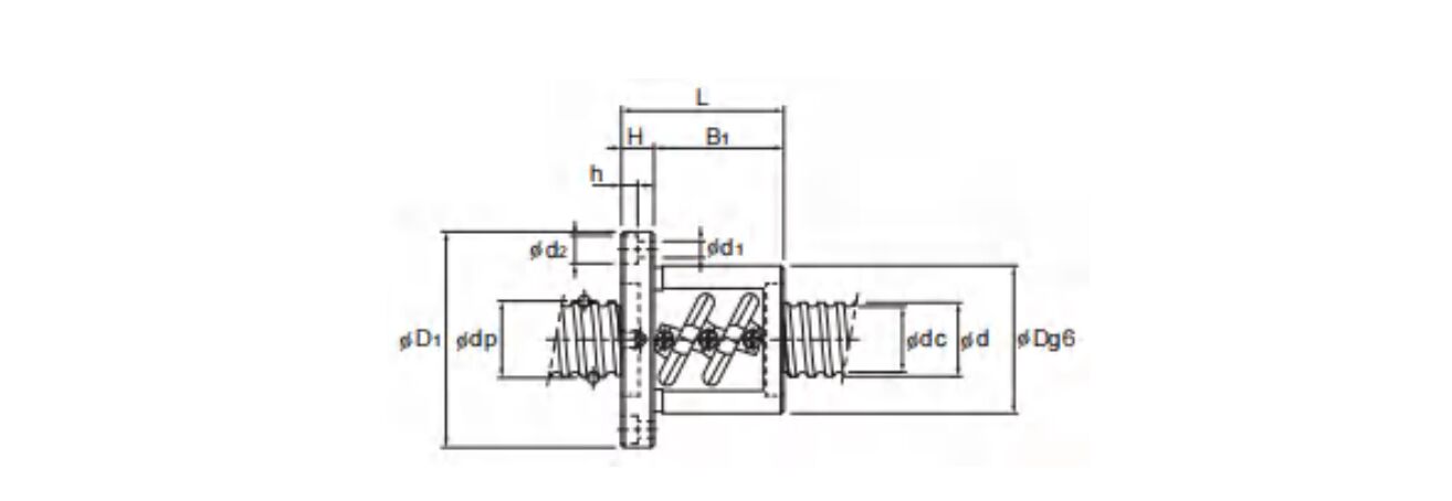
| Nut dimensions | Screw shaft inertial moment/mm |
Nut masG |
Shaft mass |
|||||||
| Outer diameter |
Flange diameter |
Overall length |
Lubrcation hole |
|||||||
| D | D₁ | Li | H | B₁ | PCD | dixd₂xh | A | kg m²/mm | kg | kg/m |
| 102 | 144 | 81 | 18 | 63 | 122 | 11×17.5X11 | 7.05X10² | 4.19 | 16.43 | |
| 102 | 144 | 111 | 18 | 93 | 122 | 11×17.5×11 | 7.05X10⁻² | 5.36 | 16.43 | |
| 102 | 144 | 141 | 18 | 123 | 122 | 11×17.5×11 | 7.05X10⁻² | 6.54 | 16.43 | |
| 105 | 147 | 93 | 18 | 75 | 125 | 11×17.5×11 | 7.05×10² | 5.01 | 16.29 | |
| 105 | 147 | 107 | 18 | 89 | 125 | 11×17.5×11 | 7.05X10⁻² | 5.6 | 16.29 | |
| 105 | 147 | 105 | 18 | 87 | 125 | 11×17.5×11 | 7.05×10⁻² | 5.52 | 16.29 | |
| 105 | 147 | 129 | 18 | 111 | 125 | 11×17.5×1l | 7.05X10⁻² | 6.54 | 16.29 | |
| 105 | 147 | 165 | 18 | 147 | 125 | 11×17.5×11 | 7.05X10⁻² | 8.07 | 16.29 | |
| 110 | 158 | 116 | 25 | 91 | 133 | 14×20X13 | 7.05×10⁻² | 7.4 | 15.46 | |
| 110 | 158 | 164 | 25 | 139 | 133 | 14×20×13 | 7.05X10⁻² | 9.73 | 15.46 | |
| 112 | 158 | 127 | 28 | 99 | 134 | 14×20X13 | Rc1/8 (PT1/8 |
7.05×10⁻² | 8.4 | 16.1 |
| 112 | 158 | 187 | 28 | 159 | 134 | 14×20×13 | 7.05×10⁻² | 11.45 | 16.1 | |
| 108 | 154 | 77 | 22 | 55 | 130 | 14×20×13 | 7.05×10⁻² | 4.57 | 21.93 | |
| 108 | 154 | 107 | 22 | 85 | 130 | 14×20×13 | 1.21×10- | 5.77 | 21.93 | |
| 108 | 154 | 137 | 22 | 115 | 130 | 14X20×13 | 1.21×10⁻¹ | 6.98 | 21.93 | |
| 115 | 161 | 87 | 22 | 65 | 137 | 14×20×13 | 1.21×10⁻¹ | 5.8 | 21.14 | |
| 115 | 161 | 123 | 22 | 101 | 137 | 14×20×13 | 1.21X10- | 7.56 | 21.14 | |
| 122 | 184 | 160 | 24 | 136 | 152 | 18×26×17.5 | 1.21×10⁻¹ | 11.82 | 20.85 | |
| 122 | 180 | 127 | 28 | 99 | 150 | 18×26×17.5 | 1.21X10- | 10.1 | 21.57 | |
| 122 | 180 | 187 | 28 | 159 | 150 | 18×26×17.5 | 1.21X10- | 13.58 | 21.57 | |

| Model No. | Screw shaft outer diameter |
Lead | Ball center- to-center diameter |
Thread minor diameter |
No.of loaded circuits |
Basic load rating | Rigidity k N/μm |
|
Ca kN |
Coa kN |
|||||||
| d | ph | dp | dc | Rows xturns | ||||
| FDW7010-2.5 | 70 | 10 | 71.75 | 64.5 | 1×2.5 | 36.8 | 123.5 | 590 |
| FDW7010-5 | 70 | 10 | 71.75 | 64.5 | 2×2.5 | 66.9 | 247 | 1140 |
| FDW7010-7.5 | 70 | 10 | 71.75 | 64.5 | 3×2.5 | 94.9 | 371.4 | 1680 |
| FDW 7012-2.5 | 70 | 12 | 72 | 64.2 | 1×2.5 | 43.5 | 139.2 | 600 |
| FDW7012-5 | 70 | 12 | 72 | 64.2 | 2×2.5 | 78.9 | 278.3 | 1160 |
| FDW 7012-7.5 | 70 | 12 | 72 | 64.2 | 3×2.5 | 111.7 | 417.5 | 1710 |
| FDW7020-5 | 70 | 20 | 72.7 | 62.9 | 2×2.5 | 153.9 | 514.5 | 1550 |
| FDW8010-2.5 | 80 | 10 | 81.75 | 75.2 | 1×2.5 | 38.9 | 141.1 | 650 |
| FDW 8010-5 | 80 | 10 | 81.75 | 75.2 | 2×2.5 | 70.6 | 283.2 | 1270 |
| FDW 8010-7.5 | 80 | 10 | 81.75 | 75.2 | 3×2.5 | 100 | 424.3 | 1860 |
| FDW 8020A-2.5 | 80 | 20 | 82.7 | 72.9 | 1×2.5 | 90.1 | 294 | 890 |
| FDW8020A-5 | 80 | 20 | 82.7 | 72.9 | 2×2.5 | 163.7 | 589 | 1720 |
| FDW 8020A-7.5 | 80 | 20 | 82.7 | 72.9 | 3×2.5 | 231.6 | 883.2 | 2520 |
| FDW 10020A-2.5 | 100 | 20 | 102.7 | 92.9 | 1×2.5 | 99 | 368.5 | 2110 |
| FDW 10020A-5 | 100 | 20 | 102.7 | 92.9 | 2×2.5 | 179.3 | 737 | 4080 |
| FDW10020A-7.5 | 100 | 20 | 102.7 | 92.9 | 3×2.5 | 253.8 | 1105.4 | 6010 |
| Nut dimensions | Screw shaft inertial moment/mm |
Nut mass |
Shaft masS |
|||||||
| Outer diameter |
Flange diameter |
Overall length |
Lubrication hole |
|||||||
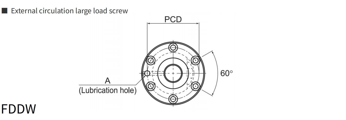
| D | D₁ | L₁ | H | B₁ | PCD | d₁xd₂xh | A | kg m²/mm | kg | kg/m |
| 125 | 167 | 81 | 18 | 63 | 145 | 11×17.5×11 | 1.85×10⁻¹ | 5.8 | 27.4 | |
| 125 | 167 | 111 | 18 | 93 | 145 | 11×17.5×11 | 1.85×10-¹ | 7.49 | 27.4 | |
| 125 | 167 | 141 | 18 | 123 | 145 | 11×17.5×11 | 1.85×10⁻¹ | 9.19 | 27.4 | |
| 128 | 170 | 93 | 18 | 75 | 148 | 11×17.5×11 | 1.85×10⁻¹ | 6.89 | 27.24 | |
| 128 | 170 | 129 | 18 | 111 | 148 | 11×17.5×11 | 1.85X10⁻¹ | 9.08 | 27.24 | |
| 128 | 170 | 165 | 18 | 147 | 148 | 11×17.5×11 | 1.85×10⁻¹ | 11.26 | 27.24 | |
| 130 | 186 | 185 | 28 | 157 | 158 | 18×26×17.5 | 3.16X10⁻¹ | 14.5 | 27 | |
| 130 | 176 | 77 | 22 | 55 | 152 | 14×20×13 | Rc1/8 (PT1/8) |
3.16×10⁻¹ | 5.9 | 36.26 |
| 130 | 176 | 107 | 22 | 85 | 152 | 14×20×13 | 3.16X10⁻¹ | 7.53 | 36.26 | |
| 130 | 176 | 137 | 22 | 115 | 152 | 14×20×13 | 3.16×10⁻¹ | 9.15 | 36.26 | |
| 143 | 204 | 127 | 28 | 99 | 172 | 18×26×17.5 | 3.16×10⁻¹ | 12.68 | 35.81 | |
| 143 | 204 | 187 | 28 | 159 | 172 | 18×26×17.5 | 3.16×10⁻¹ | 17.12 | 35.81 | |
| 143 | 204 | 247 | 28 | 219 | 172 | 18×26×17.5 | 3.16X10⁻¹ | 21.56 | 35.81 | |
| 170 | 243 | 131 | 32 | 99 | 205 | 22×32×21.5 | 7.71×10⁻¹ | 18.28 | 57.13 | |
| 170 | 243 | 191 | 32 | 159 | 205 | 22×32×21.5 | 7.71×10-¹ | 24.2 | 57.13 | |
| 170 | 243 | 251 | 32 | 219 | 205 | 22×32×21.5 | 7.71×10⁻¹ | 30.12 | 57.13 | |
| Model No. | Screw shaft outer diameter |
Lead | Ball center- to-center diameter |
Thread minor diameter |
No.of loaded circuits |
Basic load rating | Rigidity k N/μm |
|
Model No. kN |
Model No. kN |
|||||||
| d | ph | dp | dc | Rows xturns | ||||
| FDDW 5010-7.5 | 10 | 10 | 51.75 | 44.4 | 3×2.5 | 82.5 | 264.4 | 2580 |
| FDDW5510-2.5 | 55 | 10 | 56.75 | 49.5 | 1×2.5 | 33.4 | 97 | 970 |
| FDDW5510-5 | 55 | 10 | 56.75 | 49.5 | 2×2.5 | 60.7 | 194 | 1890 |
| FDDW5510-7.5 | 55 | 10 | 56.75 | 49.5 | 3×2.5 | 85.9 | 291.1 | 2770 |
| FDDW 5512-2.5 | 55 | 12 | 57 | 49.2 | 1×2.5 | 39.3 | 108.8 | 990 |
| FDDW5512-3 | 55 | 12 | 57 | 49.2 | 2×1.5 | 46 | 131.3 | 1180 |
| FDDW5512-3.5 | 55 | 12 | 57 | 49.2 | 1×3.5 | 52.4 | 152.9 | 1360 |
| FDDW 5512-5 | 55 | 12 | 57 | 49.2 | 2×2.5 | 71.3 | 218.5 | 1920 |
| FDDW 5512-7.5 | 55 | 12 | 57 | 49.2 | 3×2.5 | 100.9 | 327.3 | 2830 |
| FDDW5516-2.5 | 55 | 16 | 57.7 | 47.9 | 1×2.5 | 76.1 | 201.9 | 1310 |
| FDDW5516-5 | 55 | 16 | 57.7 | 47.9 | 2X2.5 | 138.2 | 402.8 | 2550 |
| FDDW5520-2.5 | 55 | 20 | 57.7 | 47.9 | 1×2.5 | 76 | 201.9 | 1320 |
| FDDW 5520-5 | 55 | 20 | 57.7 | 47.9 | 2×2.5 | 138.2 | 403.8 | 2550 |
| FDDW 6310-2.5 | 63 | 10 | 64.75 | 57.7 | 1×2.5 | 35.4 | 111.7 | 1090 |
| FDDW6310-5 | 63 | 10 | 64.75 | 57.7 | 2×2.5 | 64.2 | 222.5 | 2100 |
| FDDW6310-7.5 | 63 | 10 | 64.75 | 57.7 | 3×2.5 | 90.9 | 334.2 | 3090 |
| FDDW6312A-2.5 | 63 | 12 | 65.25 | 56.3 | 1×2.5 | 48.1 | 139.2 | 1120 |
| FDDW6312A-5 | 63 | 12 | 65.25 | 56.3 | 2×2.5 | 87.4 | 278.3 | 2160 |
| FDDW 6316-2.5 | 63 | 16 | 65.7 | 55.9 | 1×2.5 | 81.1 | 231.3 | 1470 |
| FDDW6316-5 | 63 | 16 | 65.7 | 55.9 | 2×2.5 | 147 | 462.6 | 2840 |
| FDDW6320-2.5 | 63 | 20 | 65.7 | 55.9 | 1×2.5 | 81 | 231.3 | 1470 |
| FDDW 6320-5 | 63 | 20 | 65.7 | 55.9 | 2×2.5 | 147 | 463.5 | 2640 |
| Nut dimensions | Screw shaft inertial moment/mm |
Nut masg |
Shaft mas5S |
Allowable rotationa specO |
|||||||
| Outer diameter |
Flange diameter |
Overall length |
Lubrication hole |
||||||||
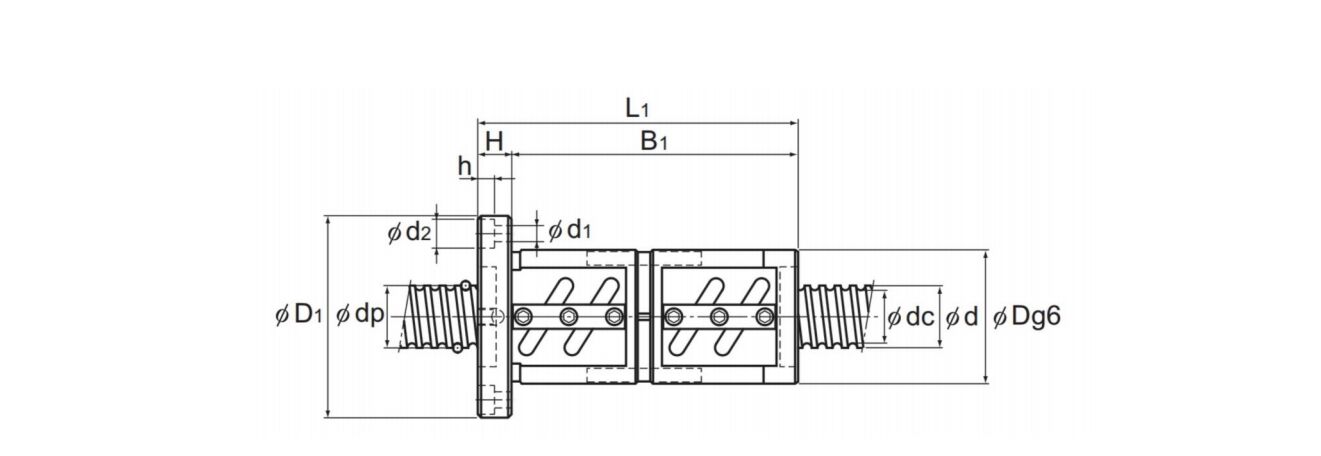
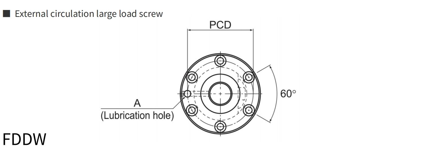
| D | D₁ | Li | H | B₁ | PCD | dixdxh | A | kg m²/mm | kg | kg/m | min- |
| 65 | 106 | 146 | 18 | 128 | 85 | 11X17.5X11 | 4.82×10⁻⁶ | 9.19 | 14.16 | 2510 | |
| 102 | 144 | 141 | 18 | 123 | 122 | 11×17.5×11 | 7.05×10⁻² | 6.54 | 16.43 | 1230 | |
| 102 | 144 | 201 | 18 | 183 | 122 | 11X17.5×11 | 7.05×10⁻² | 8.88 | 16.43 | 1230 | |
| 102 | 144 | 261 | 18 | 243 | 122 | 11×17.5×11 | 7.05×10⁻² | 11.23 | 16.43 | 1230 | |
| 105 | 147 | 165 | 18 | 147 | 125 | 11X17.5×11 | 7.05X10⁻² | 8.07 | 16.29 | 1220 | |
| 105 | 147 | 191 | 18 | 173 | 125 | 11×17.5×11 | 7.05X10⁻² | 9.17 | 16.29 | 1220 | |
| 105 | 147 | 189 | 18 | 171 | 125 | 11X17.5×11 | 7.05×10⁻² | 9.09 | 16.29 | 1220 | |
| 105 | 147 | 237 | 18 | 219 | 125 | 11×17.5×11 | 7.05×10⁻² | 11.13 | 16.29 | 1220 | |
| 105 | 147 | 309 | 18 | 291 | 125 | 11X17.5×11 | 7.05×10⁻² | 14.19 | 16.29 | 1220 | |
| 110 | 158 | 196 | 25 | 171 | 133 | 14×20×13 | 7.05×10⁻² | 11.28 | 15.46 | 1210 | |
| 110 | 158 | 292 | 25 | 267 | 133 | 14X20X13 | 7.05X10⁻² | 15.94 | 15.46 | 1210 | |
| 112 | 158 | 227 | 28 | 199 | 134 | 14×20×13 | 7.05×10⁻² | 13.49 | 16.1 | 1210 | |
| 112 | 158 | 347 | 28 | 319 | 134 | 14×20X13 | 7.05X10⁻² | 19.61 | 16.1 | 1210 | |
| 108 | 154 | 137 | 22 | 115 | 130 | 14×20×13 | 1.21×10-¹ | 6.98 | 21.93 | 1080 | |
| 108 | 154 | 197 | 22 | 175 | 130 | 14×20×13 | 1.21X10- | 9.4 | 21.93 | 1080 | |
| 108 | 154 | 257 | 22 | 235 | 130 | 14X20X13 | 1.21X10- | 11.81 | 21.93 | 1080 | |
| 115 | 161 | 159 | 7 | 137 | 137 | 14×20×13 | 1.21X10- | 9.32 | 21.14 | 1070 | |
| 115 | 161 | 231 | 22 | 209 | 137 | 14×20×13 | 1.21X10- | 12.84 | 21.14 | 1070 | |
| 122 | 184 | 208 | 24 | 184 | 152 | 18×26×17.5 | 1.21×10⁻¹ | 14.61 | 20.85 | 1060 | |
| 122 | 184 | 304 | 24 | 280 | 152 | 18×26×17.5 | 1.21×10⁻¹ | 20.19 | 20.85 | 1060 | |
| 122 | 180 | 227 | 28 | 199 | 150 | 18×26×17.5 | 1.21×10-¹ | 15.91 | 20.85 | 1060 | |
| 122 | 180 | 347 | 28 | 319 | 150 | 18×26×17.5 | 1.21X10- | 22.88 | 20.85 | 1060 | |
| Model No. | Screw shaft outer diameter |
Lead | Ballcenter- to-center diameter |
Thread minor diameter |
No.of loaded circuits |
Basic load rating | Rigidity k N/μm |
|
Model No. kN |
Model No. kN |
|||||||
| d | ph | dp | dc | RoWs xturns | ||||
| FDDW7010-2.5 | 70 | 10 | 71.75 | 64.5 | 1×2.5 | 36.8 | 123.5 | 1180 |
| FDDW7010-5 | 70 | 10 | 71.75 | 64.5 | 2×2.5 | 66.9 | 247 | 2280 |
| FDDW7010-7.5 | 70 | 10 | 71.75 | 64.5 | 3×2.5 | 94.9 | 371.4 | 3350 |
| FDDW7012-25 | 70 | 12 | 72 | 64.2 | 1×2.5 | 43.5 | 139.2 | 1200 |
| FDDW7012-5 | 70 | 12 | 72 | 64.2 | 2×1.5 | 78.9 | 278.3 | 2320 |
| FDDW7012-7.5 | 70 | 12 | 72 | 64.2 | 3×3.5 | 111.7 | 714.5 | 3420 |
| FDDW7020-5 | 70 | 20 | 72.7 | 62.9 | 2×2.5 | 153.9 | 514.5 | 3090 |
| FDDW8010-2.5 | 80 | 10 | 81.75 | 75.2 | 1×2.5 | 38.9 | 141.1 | 1300 |
| FDDW8010-5 | 80 | 10 | 81.75 | 75.2 | 2×2.5 | 70.6 | 283.2 | 2530 |
| FDDW8010-7.5 | 80 | 10 | 81.75 | 75.2 | 3×2.5 | 100 | 424.3 | 3720 |
| FDDW8012-5 | 80 | 12 | 82.3 | 74.1 | 2×2.5 | 96.5 | 353.8 | 2620 |
| FDDW8020A-2.5 | 80 | 20 | 82.7 | 72.9 | 1×2.5 | 90.1 | 294 | 1770 |
| FDDW 8020A-5 | 80 | 20 | 82.7 | 72.9 | 2×2.5 | 163.7 | 589 | 3430 |
| FDDW 10020A-2.5 | 100 | 20 | 102.7 | 92.9 | 1×2.5 | 99 | 368.5 | 2110 |
| FDDW 10020A-5 | 100 | 20 | 102.7 | 92.9 | 2×2.5 | 179.3 | 737 | 4080 |
| FDDW 10020A-7.5 | 100 | 20 | 102.7 | 92.9 | 3×2.5 | 253.8 | 1105.4 | 6010 |
| Nut dimensions | Screw shaft inertial moment/mm |
Nut mas5 |
Shaft masS |
Allowable rotationa spsen |
|||||||
| Outer diameter |
Flange diameter |
Overall length |
Lubrication hole |
||||||||
| D | D₁ | Li | H | B₁ | PCD | d₁xd₂xh | A | kg m²/mm | kg | kg/m | min: |
| 125 | 167 | 141 | 18 | 123 | 145 | 11×17.5×11 | 1.85X10⁻⁵ | 9.19 | 27.4 | 970 | |
| 125 | 167 | 201 | 18 | 183 | 145 | 11×17.5×11 | 1.85×10⁻⁵ | 12.57 | 27.4 | 970 | |
| 125 | 167 | 261 | 18 | 243 | 145 | 11×17.5×11 | 1.85X10⁻⁵ | 15.96 | 27.4 | 970 | |
| 128 | 170 | 165 | 18 | 147 | 148 | 11×17.5×11 | 1.85×10⁻⁵ | 11.26 | 27.24 | 970 | |
| 128 | 170 | 237 | 18 | 219 | 148 | 11×17.5×11 | 1.85×10-⁵ | 15.63 | 27.24 | 970 | |
| 128 | 170 | 309 | 18 | 291 | 148 | 11×17.5×11 | 1.85×10⁻⁵ | 20 | 27.24 | 970 | |
| 130 | 186 | 325 | 28 | 297 | 158 | 18×26×17.5 | 1.85×10⁻⁵ | 23.4 | 27 | 960 | |
| 130 | 176 | 137 | 22 | 115 | 152 | 14×20×13 | Rc1/8 (PT1/8) |
3.16×10⁻⁵ | 9.15 | 36.26 | 850 |
| 130 | 176 | 197 | 22 | 175 | 152 | 14×20×13 | 3.16×10⁻⁵ | 12.41 | 36.26 | 850 | |
| 130 | 176 | 257 | 22 | 235 | 152 | 14×20×13 | 3.16×10⁻⁵ | 15.67 | 36.26 | 850 | |
| 135 | 181 | 231 | 22 | 209 | 157 | 14×20×13 | 3.16X10⁻⁵ | 16.02 | 35.26 | 850 | |
| 143 | 204 | 227 | 28 | 199 | 172 | 18×26×17.5 | 3.16×10⁻⁵ | 20.08 | 35.1 | 840 | |
| 143 | 204 | 347 | 28 | 319 | 172 | 18×26×17.5 | 3.16×10⁻⁵ | 28.97 | 35.81 | 840 | |
| 170 | 243 | 231 | 32 | 199 | 205 | 22×32×21.5 | 7.71×10⁻⁵ | 28.15 | 57.13 | 680 | |
| 170 | 243 | 351 | 32 | 319 | 205 | 22×32×21.5 | 7.71×10⁻⁵ | 39.99 | 57.13 | 680 | |
| 170 | 243 | 471 | 32 | 439 | 205 | 22×32×21.5 | 7.71×10⁻⁵ | 51.84 | 57.13 | 680 | |
Copyright © Jingpeng Machinery&Equipment(Shanghai) Co.,Ltd All Rights Reserved